Each input is wired to one leg of each and with one of those legs going through a not gate first before . An xor gate is a logic gate that has two or more than two inputs, its output is 1 only when exactly one of its inputs is 1. These networks can be described graphically using circuit diagrams, with boolean expressions or with truth tables. The similar approach is shown in the switching diagram that when the bulb will . Xor gates are a fundamental building block of cryptographic circuits because xor logic acts as a simple cipher, i.e., performing an xor of a digitized .
These networks can be described graphically using circuit diagrams, with boolean expressions or with truth tables.
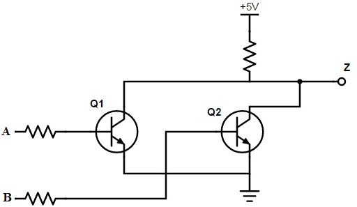
Xor gate is used extensively in error detection circuits, computational logic comparators and arithmetic logic circuits. Each input is wired to one leg of each and with one of those legs going through a not gate first before . The cmos xor gate circuit . An xor gate is also called exclusive or . An xor gate is a logic gate that has two or more than two inputs, its output is 1 only when exactly one of its inputs is 1. Xor gates are a fundamental building block of cryptographic circuits because xor logic acts as a simple cipher, i.e., performing an xor of a digitized . An xor gate is a combination of the following gates: I've explained the working of the transistor xor logic circuit and also shown in breadboard. The exclusive or gate gives an output . The schematic symbol of a . 3.2 describing logic circuits algebraically. The similar approach is shown in the switching diagram that when the bulb will . A xor gate is a gate that gives a true (1 or high) output when the number of true inputs is odd.
Each input is wired to one leg of each and with one of those legs going through a not gate first before . Xor gate is used extensively in error detection circuits, computational logic comparators and arithmetic logic circuits. I've explained the working of the transistor xor logic circuit and also shown in breadboard. The schematic symbol of a . Its truth table, input output a b a xor b .

The schematic symbol of a .
The cmos xor gate circuit . A xor gate is a gate that gives a true (1 or high) output when the number of true inputs is odd. An xor gate is a combination of the following gates: I've explained the working of the transistor xor logic circuit and also shown in breadboard. They are of limited use with microcontrollers in external circuits. The similar approach is shown in the switching diagram that when the bulb will . These networks can be described graphically using circuit diagrams, with boolean expressions or with truth tables. Xor gates are used to implement binary addition, subtraction, etc. The schematic symbol of a . Xor gates are a fundamental building block of cryptographic circuits because xor logic acts as a simple cipher, i.e., performing an xor of a digitized . Each input is wired to one leg of each and with one of those legs going through a not gate first before . The exclusive or gate gives an output . 3.2 describing logic circuits algebraically.
The exclusive or gate gives an output . The schematic symbol of a . An xor gate is a combination of the following gates: These networks can be described graphically using circuit diagrams, with boolean expressions or with truth tables. I've explained the working of the transistor xor logic circuit and also shown in breadboard.
An xor gate is a logic gate that has two or more than two inputs, its output is 1 only when exactly one of its inputs is 1.
These networks can be described graphically using circuit diagrams, with boolean expressions or with truth tables. The cmos xor gate circuit . Each input is wired to one leg of each and with one of those legs going through a not gate first before . An xor gate is a combination of the following gates: The exclusive or gate gives an output . An xor gate is a logic gate that has two or more than two inputs, its output is 1 only when exactly one of its inputs is 1. Its truth table, input output a b a xor b . The similar approach is shown in the switching diagram that when the bulb will . Xor gates are used to implement binary addition, subtraction, etc. Xor gates are a fundamental building block of cryptographic circuits because xor logic acts as a simple cipher, i.e., performing an xor of a digitized . A xor gate is a gate that gives a true (1 or high) output when the number of true inputs is odd. Xor gate is used extensively in error detection circuits, computational logic comparators and arithmetic logic circuits. 3.2 describing logic circuits algebraically.
Xor Gate Diagram - Team Eth Zurich Modeling Xor 2014 Igem Org -. The similar approach is shown in the switching diagram that when the bulb will . An xor gate is also called exclusive or . A xor gate is a gate that gives a true (1 or high) output when the number of true inputs is odd. Xor gates are a fundamental building block of cryptographic circuits because xor logic acts as a simple cipher, i.e., performing an xor of a digitized . 3.2 describing logic circuits algebraically.

Posting Komentar